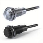
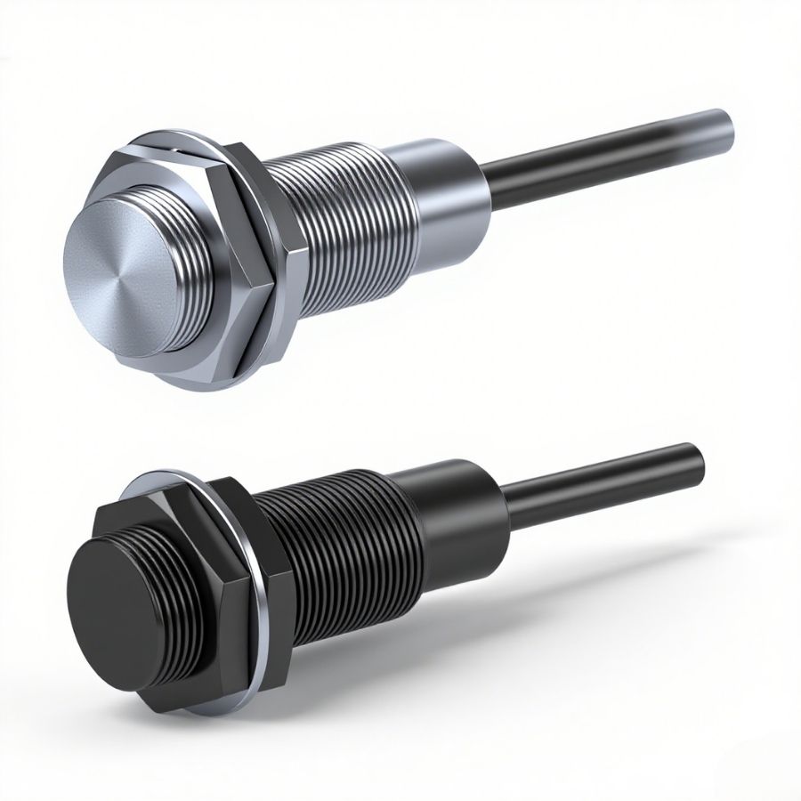
Autonics PRF Series Cylindrical Inductive All-metal Proximity Switch(DC 2-wire type)

— Offering flush & splash-proof models, with 8–30mm detection diameters, 0–7mm sensing distances. Features fast response (50–200Hz), IP67 protection, -25~70℃ operation, stainless steel build, and multiple protection circuits. Ideal for industrial automation.
Autonics PRF Series Cylindrical Inductive All-metal Proximity Switch(DC 2-wire type)
RFQ Now For 10% Off!
Technical Features
Products + Accessories Selection:
| Mounting type | Flush type | |||
| Standard type | PRF☐T08-1.5DO-☐ | PRF☐T12-2DO-☐ | PRF☐T18-5DO-☐ | PRF☐T30-10DO-☐ |
| Splash-proof type | PRFA ☐T08-1.5DO-☐ | PRFA ☐T12-2DO-☐ | PRFA ☐T18-5DO-☐ | PRFA ☐T30-10DO-☐ |
| Sensing side diameter | Ø 8 mm | Ø 12 mm | Ø 18 mm | Ø 30 mm |
| Sensing distance 01) | 1.5 mm | 2 mm | 5 mm | 10 mm |
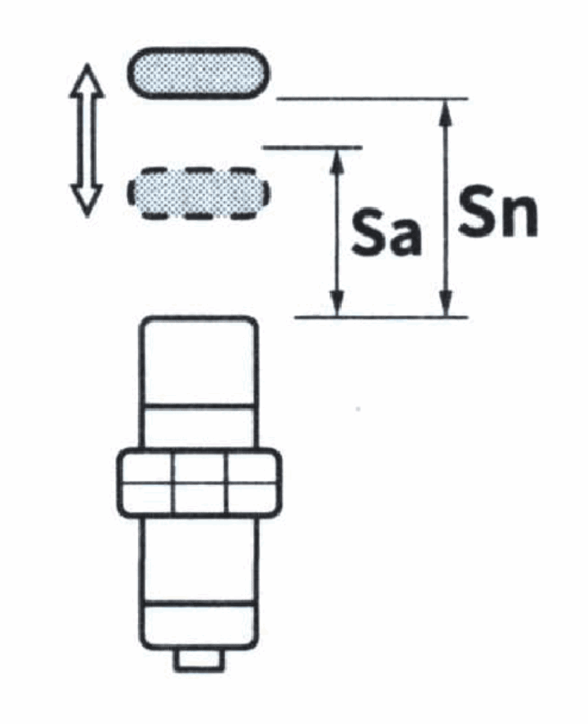
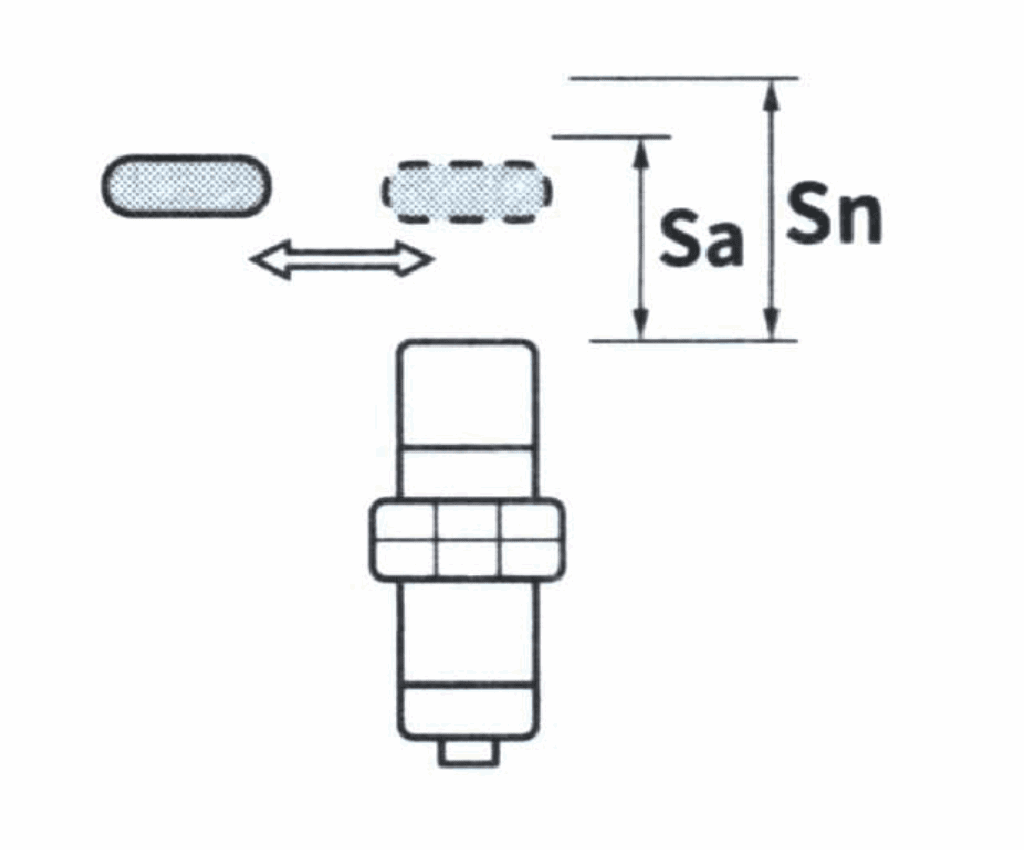
| Setting distance | 0 ~ 1.05 mm | 0 ~ 1.4 mm | 0 ~ 3.5 mm | 0 ~ 7 mm |
| Standard sensing target: Iron | 15% of sensing distance | |||
| Response frequency 02) | 200 Hz | 100 Hz | 80 Hz | 50 Hz |
| Influence of temperature | Within ±20% of sensing distance at 20°C ambient temperature | |||
| Indicator | Operation indicator (red) | |||
| Approvals | ||||
| Product weight (including packaging) | ≈ 55 g (≈ 80 g) | ≈ 83 g (≈ 110 g) | ≈ 97 g (≈ 132 g) | ≈ 170 g (≈ 225 g) |
- Please use the sensor with the nut tightened. Otherwise, the warranty may not be valid.
- The response frequency is the average value. The measurement conditions are using the standard sensing target, with the width of the target being twice the standard sensing target, and the setting distance being half of the sensing distance.
| Power supply voltage | 12-24 VDC (ripple P-P: ≤ 10%), use with power supply range: 10-30 VDC |
| Leakage current | ≤ 0.8 mA |
| Control output | 3 ~ 100 mA |
| Residual voltage | ≤ 3.5 V |
| Protection circuit | Surge protection circuit, output short-circuit overcurrent protection circuit, power supply reverse polarity protection circuit |
| Insulation resistance | ≥ 50 MΩ (500 VDC megger) |
| Dielectric strength | 1,000 VAC ~ 50/60 Hz 1 min (between all terminals and case) |
| Vibration | 10 ~ 55 Hz (period 1 min) amplitude 1.5 mm X, Y, Z directions 2 hours each |
| Shock | 1,000 m/s² (≈ 100 G) X, Y, Z directions 10 times each (Sensing side Ø 8 mm: 500 m/s² (≈ 50 G) X, Y, Z directions 10 times each) |
| Ambient temperature 01) | -25 ~ 70 °C, storage: -25 ~ 70 °C (no freezing, no condensation) |
| Ambient humidity | 35 ~ 95 %RH, storage: 35 ~ 95 %RH (no freezing, no condensation) |
| Protection degree | IP67 (IEC standard) |
| Connection type | Cable outgoing type / Cable outgoing connector type |
| Cable specification 02) | Sensing side Ø 8 mm: Ø 4 mm, 2-core Sensing side Ø 12 mm, Ø 18 mm, Ø 30 mm: Ø 5 mm, 2-core |
| Conductor specification | AWG 22 (0.08 mm, 60-core), insulation outer diameter: Ø 1.25 mm |
| Connector specification | M12 connector |
| Material | Standard type: Case / Nut: SUS303, Washer: SUS304, Sensing side 03): SUS303 |
| Splash-proof type: Case / Nut: SUS303 (PTFE non-stick coating), Washer: SUS304, Sensing side 03): SUS303 (PTFE non-stick coating) |
- UL certified for ambient temperature of 40°C.
- Cable outgoing type: 2 m (option: 5 m), Cable outgoing connector type: 300 mm.
- Thickness: 0.8 mm (Sensing side Ø 8mm: 0.4 mm).
Setting Distance Calculation Formula
The shape, size, and material of the sensing object all affect the sensing distance. For stable detection, please install within 70% of the sensing distance.

Influence of Mutual Interference and Surrounding Metal
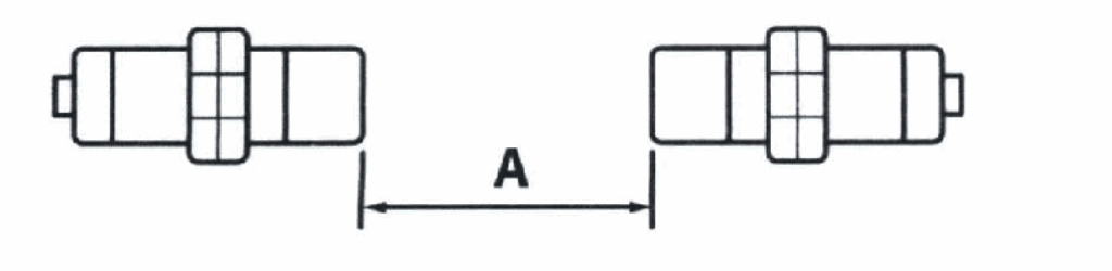
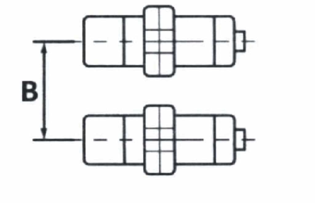
■ Mutual Interference
As shown in the figure below, when two or more proximity switches are installed face-to-face or side-by-side, malfunctions may occur due to frequency interference. The installation spacing must meet the requirements of the table below.
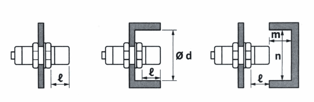
■ Influence of Surrounding Metal
If metal is present around the proximity switch, it may cause malfunctions such as poor resetting. To prevent malfunctions, the installation spacing must meet the requirements of the table below.
(Unit: mm)
| Sensing side | Ø 8 mm | Ø 12 mm | Ø 18 mm | Ø 30 mm | |
|---|---|---|---|---|---|
| Item | – | – | – | – | – |
| A | – | 35 | 40 | 65 | 110 |
| B | – | 30 | 35 | 60 | 100 |
| l | – | 0 | 0 | 0 | 0 |
| Ød | – | 8 | 12 | 18 | 30 |
| m | – | 4.5 | 8 | 20 | 40 |
| n | – | 30 | 40 | 60 | 100 |
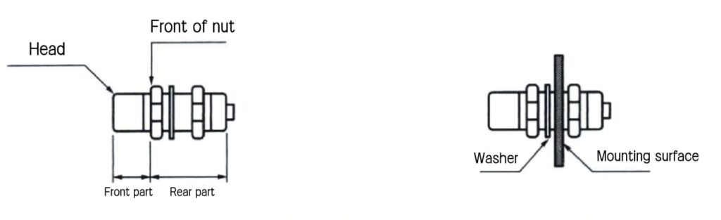
Allowable Installation Torque
When tightening the nut, please use the provided washer. The allowable nut torque is the value when using the attached washer and inserting as shown in the figure below.
| Sensing side | Ø 8 mm | Ø 12 mm | Ø 18 mm | Ø 30 mm | |
|---|---|---|---|---|---|
| Strength | – | – | – | – | – |
| Torque | – | 3.5 N·m | 25 N·m | 70 N·m | 180 N·m |


